Wednesday, March 24, 2010

Steering box brace and roof rack

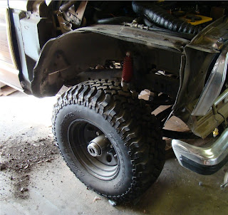
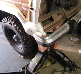
The steering box brace is one of those upgrades that will only serve a purpose off-road, but it was worth it. Right now, my steering box is performing beautifully--no leaks, easy and fluid turns, no slop in the steering wheel at all. What this brace does, thanks to TT Fabworks, is lock the steering box tight to BOTH frame rails. (It's bolted to the left rail as its standard mounting point, and this brace ties it as well to the right.) As a result, in an off-road situation the box mounting points won't be stressed or torqued much, if at all, when the tires are in a jam.
The brace is a steel tube that T's into a flat steel plate that is bolted to the inner right frame rail directly across from the steering box. My frame rail might be slightly out of true from the earlier mentioned front right ding courtesy of the PO. As a result, I had to use some Grade 8 washers to adjust the fitment of the brace against the right rail (a space is welded into the bracket to account for the offset mounting holes in the rail itself). Before I added the washers, as the brace extended over to the steering box, it didn't line up properly for the mounting brackets. Two washers later, it's good. (While we're here, note the wiring nest up above the alternator in the background. That'll be dealt with soon.)
The brace clamps around the pivot shaft of the steering box just above the pitman arm. Once it's in place and lined up, with the nut and bolt on the outside of the steering box set loosely in place, just use a pair of vice grips to hold the longer legs of the bracket in place against the extension arm before drilling holes for the mounting hardware. This gets a custom fit every time, specific to each application.
This was a half-hour project, mainly because of the alignment issues. Here you can see the brace in its entirety.

And now for the roof rack.
I found this roof rack on the same '88 GW at the San Bernardino PAP. I and several others on the IFSJA forum are picking this rig clean. It was $18 out the gate, and it's in great shape. Now, most FSJers refer to these as vanity racks because they aren't as rugged as a safari-style rack. But those are hundreds of dollars, and I don't like to carry a lot on top of my vehicles anyway, so this'll do for me.
To get the project started, I had to pull the headliner trim pieces and drop my exceptionally ugly headliner down a few inches to access the underside of the roof. Then it was a matter of disconnecting the dome lights and rear seatbelt attachment points so that I could drop it down fully.
That's when I learned a little more about the complexity of the project at hand and the usefulness for doing it. By pulling the headliner out completely, I could see the roof support cross-members, two of which were dented/sagging (the one farthest forward in this pic and the one closest to me).
Here's a closeup showing how the cross-member is supposed to be attached (with some kind of adhesive) and is bent down.
My solution of choice. I use some industrial adhesive, a 4x4 leftover from my new fence, and a small carjack to get the roof and the cross-members back into some semblance of their original position. An inelegant solution, to be sure, but I'm just looking for better, not good. Besides, I bought this thing in part because it was ugly and in need of some knuckle-busting.
Below you can see the sinkholes in the roof (those metal slats are supposed to lay flat across the roof). I just worked my way around the passenger compartment, jacking up the dents and then using some metal screws to hold the roof up tight against the slats.
In the pic above you can see the mounting holes for the rack. Apparently a little rubber grommet with a metal thread insert is supposed to go in each of those holes. As a small torq-head bolt is screwed into the grommet, the rubber expands to fill the hole and hold everything tight. Um, no. I tried and was not successful in any way. Perhaps the mounting holes were expanded by a previous owner--who knows. So plan B, which should have been plan A, was sprung into action. I found some steel L-brackets, cut them at the bend, and used them to mount the rack to the roof. Here's an undershot.
I used RTV in each bolt hole to help seal things up (you can see some squeeze out from the nearer end of the bracket). And then I caulked around every metal screw I used in the slats to hold the roof in place. It's definitely water tight and will remain so.
A shot of one of the roof rack mounting points. There's a plastic "seal" sits between the roof rack's foot and the roof itself. That also was treated to some RTV (I had a lot extra) to keep things sealed up nicely.
This thing is on securely. When I grab it and move it side to side, the entire Jeep rocks and there is absolutely no play in the rack itself. While I won't be hauling cinder blocks with the rack any time soon, it's certainly not a vanity rack anymore.
It was nice to make some improvements on the roof itself as part of the rack installation. At times, over large bumps, the roof would make a buckling sound (like when an oven cools after baking bread, if that makes sense). It doesn't do that anymore because of the increased rigidity of the repaired cross-members and the increased attachment points with the metal slats.
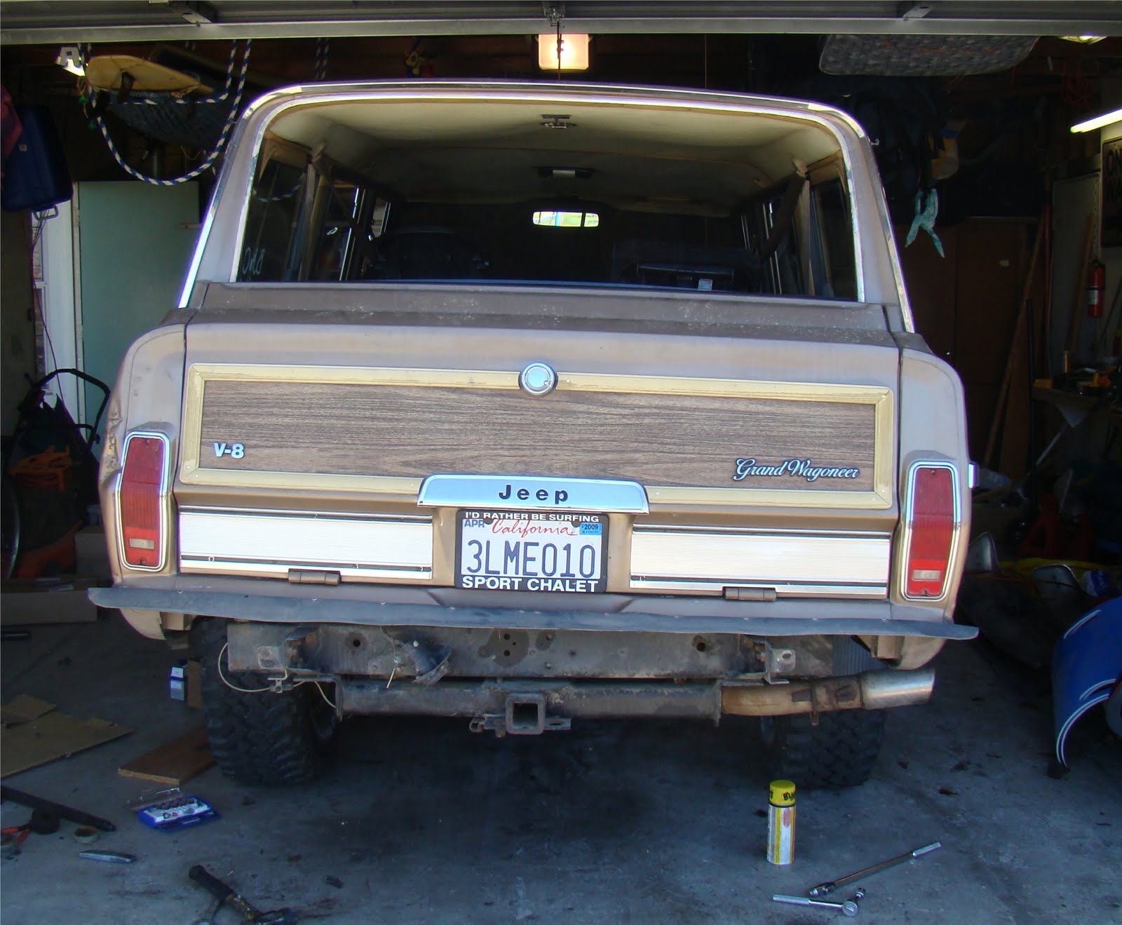
The final product...
Nath took this pic sitting up on my shoulders. He's quite the photographer.

Monday, March 22, 2010

Wiring up the fan

This wasn't too terribly complicated, except for the temp sensor that tells the fan relay to engage the fan itself. I didn't want it running all the time because that would only delay the engine warming up, which is part of the problem I had before with the stuck thermostat, so I had to come up with a more viable solution, which I did (by throwing a little money at the problem).
I'm not a fan of wiring nests, and the previous owner was a hack (the mess I had to clean up behind the stereo alone still boggles my mind). Unfortunately, however, the fan relay has a lot of wires running off of it, and its placement was limited by wire length (didn't want to splice any extensions on ). To keep the wiring clustered efficiently-ish and out of the way, I put the fan relay next to the starter relay on the passenger's fender inside the engine bay.
I'll probably come back to this area in the future and make some improvements in the layout and weather protection. Perhaps a plastic dome enclosure to shield it from random splashes or debris. I really don't want to damage the fan and have it die on me, leaving me stranded.
This was the slightly more complicated bit. I was hoping to use a manifold port for the temp sensor, but none were available. Essentially, this thing has to be in the coolant flow to know when the coolant temperature has reached the engagement point. It then sends a signal to the fan to turn on. (The engagement point is adjustable, which is nice.) The fan shuts off when the temp drops 10 degrees below that point, or when the engine is turned off.
My solution was to order an aluminum insert that gets put into the upper radiator hose, allowing the temp sensor to get screwed in there. There's also a ground wire to keep everything safe. I ran the wires down and around the battery and then back to the relay itself. It works, and it's out of the way of the moving parts of the engine. I'll probably wrap it in sleeving later.
I let the rig idle in the garage for about fifteen minutes, waiting until the fan engaged, which it did. The first time it spun, there was a bit of a rattle, but that sound hasn't returned since, so I'm okay with it. All in all, the new fan, the new radiator, the new temp sensor, and the new water temp sender are working as they should to keep the engine running cool and smooth.

Saturday, March 20, 2010

New Crossflow Radiator, Electric Fan, Thermostat, and Water Temp Sensor

A while back, I noticed the occasional small puddle on the garage floor underneath the radiator core support. It was a slightly cloudy liquid, not at all like I expected coolant to look like. But there was nowhere else it could be coming from. I couldn't find the leak itself, but the age of the radiator hoses and the radiator itself (which is the original with the Jeep, I believe), it was time to make an upgrade. Having worked a bit extra this winter session at RCC, I had the fun-funds to make the upgrade. I went with the aluminum crossflow radiator and accompanying electric fan from BJ's, designed specifically to fit the Jeep's core support radiator housing. This is the best shot I have of the original--apparently, it was too ugly to document closely. It's the black lumpy thing to the right of Nath's right hand.
So here are the new pieces to go in. I'm replacing both the radiator and the mechanical fan to improve cooling. Excess heat kills engines and transmissions, so this is a smart upgrade and well worth the part of the afternoon it requires to install. The fan (a 2400 CFM unit which pulls rather than pushes air) comes with the aluminum shroud to improve efficiency. Since the shroud for my mechanical fan was gone before I bought the Jeep, this is an added bonus.
I couldn't reuse the brass connectors on the original radiator because they were too small. But getting the plumbing figured out just required a quick trip to the local Home Depot for a pair of straight and elbow brass hose connectors for the top and the bottom. Here they are, installed, along with the brass connector that runs from the fill neck to the overflow container on the driver's side fender.


Removing the old one was simply a matter of draining the original (a few gallons total, but it took forty minutes to trickle drain--see pic below); disconnecting the transmission cooler lines, as well as the upper and lower radiator hoses; and then removing a few bolts holding the radiator to the core support. In this pic, you can also see the green corrosion at the bottom of the radiator (top middle of the pic). The hoses running across the upper third of the picture are the tranny cooler lines that run transmission fluid through the cooler that sits in front of the AC condenser (see next pic). The hoses that run out the left side of that mini-radiator (the tranny cooler) were also replaced in the upgrade process.
So now the radiator is in and all hoses are hooked up. This new one has a built-in transmission cooler that I chose to use with my existing/stock cooler to help extend transmission life. The tranny cooler was in much better shape than the radiator, probably because it is protected between the AC condenser and the grill, whereas the radiator itself is subject to whatever gets thrown up into the engine bay.
A shot of the underside with new hoses connecting everything together. No more leaks, much better flow, and a happy (i.e., cooler) engine. (Note the tight tolerances between the engine pulleys and the electrical fan. There's about a half inch right now because the old fan's double-ended bolts were extra long. I'll replace them with capped bolts later to increase the spacing.)

On to the thermostat.
While the radiator was drained and the hoses disconnected, I wanted to replace my thermostat (which opens and closes at specific temperatures to allow coolant to circulate around the engine). I'm pretty sure the one in there was bad simply because the Jeep took forever to warm up--a common sign the thermostat is stuck open. Here's what I found when I popped the thermostat housing off:
Not pretty. Lots of gunk and orange rust in there, at least partly caused by the fact that the Jeep has been sitting for a while. Closer inspection with the thermostat out. Looks like standing water has been sitting on a cast-iron engine block.
I scrapped off the old seal off the top of the block and cleaned up the housing, sanding it smooth and getting off what rust I can. With the engine rebuild coming soon, it doesn't need to be perfect.
A little liquid thermostat gasket, and it was back on the block, tightened down, and ready for some hoses. While I was working in the area, I also installed a new water temperature sender on the manifold just behind the distributor. This is the thing that sends the temp reading to the dashboard gauge so that I can tell how hot or cool the engine is running. I'm not sure the other one was bad, but it's an inexpensive part worth replacing in light of all the other cooling system changes I'm making.

Here it is, all back together. Up next, wiring the electric fan.


Sunday, February 21, 2010

Bumper rubber upgrade

Found some good rubber trim pieces on a wrecked '88 GW at the local Pick-A-Part, same one I got the fenders from, among other pieces. My five-year-old son and I pulled my Jeep's rear bumper and then got to work upgrading it. Here's what I had to start with:
Once we got it pulled, we just had to use a socket wrench to remove the screws or nuts holding the various trim bits in place. Here's the big man hard at work...
Back on and looking good.

Friday, February 19, 2010

Side marker lights

As part of the fender replacement, I had to remove the front right side marker light (which was already cracked up, dirty, and dead). Here's the gratuitous before shot:
Replacement was as easy as a call to BJ's Offroad for a new set for all four corners. I wanted, above all, to have working running lights, so I also opted for some bulbs and bulb housings. The front ones were quick and simple, with Nath helping me the whole way. The after shot, with the new fender:
The driver's side rear marker was an entirely different matter. Here's what I had to work with, thanks to the previous owner of my rig. I'm not sure what he hit or how he tried to "repair" the damage. But it was lumpy, bumpy, and quite out of true.
I couldn't get the new side marker housing to fit this mucked up area (the base is L-shaped, wrapping around the fender corner to get close to the taillight housing). So I had to get a little creative with my bandsaw. Basically, I cut off the part of the housing that wraps around the end and then scribed the remaining section to better fit the "unique contours" of the body panel. I then elongated the hole seen in the pic above (where the bulb base comes through the body to provide the bulb itself with juice) to allow for the more forward placement of the side marker base. After, I scrubbed the damaged portion of the fender around the taillight with a wire attachment on my drill to get rid of any paint flakes, followed by a quick spray of silver Rustoleum paint to retard future rusting of the area (I didn't have any gold in the garage, and I'm cheap). The final result:
Overall, I'm pleased. It works, it's sealed from the elements thanks to some clear silicon caulk, and it doesn't look bugly. I'll address the busted taillight housing later--for now, it lights up so I'm legal.

Saturday, February 13, 2010

New door panels and right front fender

On a trip to the local Pick-A-Part (with directions from a fellow member of the IFSJA.org), I grabbed a front right fender and some inner door panels, plus some other odds and ends like a vanity roof rack, door switches, and a headlight bezel. First, I tackled the door panels. My originals were adequate, but the PAP ones were cleaner and more structurally sound (they're not much more than a particle board/cardboard hybrid with vinyl over the top). The replacements had more clips to hold them on and weren't quite so beat up. Unfortunately, I didn't take any pics of this because I did it with the older kids. Here's a "final product" shot.
Why I'm replacing it. The previous owner must've hit something rather firmly. It wasn't a functionality issue. I just got tired of scraping my side on it as I walked through the garage. Plus, the new one was only fifty bucks at the PAP in San Bernardino.
Here's the run through. To remove it, there are about seventeen bolts (give or take). Six or so along the top, four between the passenger door and the body (very awkward to get to), two on and two in front of the rocker panel, and three behind the headlight and signal light up where the fender meets the front valance. Plus one on a metal rod that holds rigid the lower front portion of the fender just in front of the tire.
A pic of it off. That pile of dirt and leaves to the left of/behind the tire (notice the clean floor in the above pic) was trapped up in the fender well. No rust though, which is nice. California car.
Putting the new one on was a bit of a challenge. The biggest bite was trying to get the front valance forward enough to meet up with the newer fender. I tried heat, hammers, and a pair of floor jacks and some 4"x4" cutoffs, but I couldn't get it done. C'est la vie. While I was in there, I took care of the new headlight bezel, as well. But that's another post.
Here's the final result. I put back most of the bolts, leaving off one inside the door jamb. A little black RTV between the fender and the body at the door jamb helped keep things water tight in the cabin.

Friday, June 12, 2009

Replaced the distributor pickup and rebuilt the carburetor


I was working around in the engine bay the other day and saw that the wiring for the distributor was cobbled together like so many other things on the Jeep. The PO must've cut the wires and then simply spliced them back together with electrical tape. No wiring nuts, no heat-shrink tubing. Nothing. So I pulled apart the distributor and removed the distributor ignition pickup (at right). You can see the electrical tape and the relatively poor condition of a crucial part of the ignition system, so I bought a new one and threw it on.
Here's the new one in the distributor. The harness clip is fresh, the metal isn't corroded, the wiring is solid, all in all, much improved and a rather simple fix. I like these kinds of projects, especially because I learn a bit more about the device I'm working on, as well as the system of which it is a part.
Quick confession: I lost one of the pins that locks the rotor wheel in the center of the distributor in place, so I replaced it with the pin from a wristwatch band. Works perfectly.

Driving it to work the other day, I heard a lovely backfire--my first, believe it or not. A few blocks later, she died on me, so I coasted her to a nice spot in front of an insurance place, locked her up, and made for the cell phone. My loving and patient wife got me to work on time. I tried a few different tricks to get it going again, but to no avail. Having AAA got the rig home the next day. I did a little reading as it sat out front, exploring possible causes of a backfire. With no noticeable damage done to the exhaust system, I figured that the backfire blew out the power valve in the carb, a common occurrence.
I was in the mood for a new and interesting experience, so I got up the gumption to rebuild my carb, a Motorcraft 2150. I bought a rebuild kit from NAPA that had the power valve plus all the other goodies that I wouldn't mind replacing on the 2150.

First, I yanked the carb, but with a bit of anal retentiveness. This thing has hoses all over the place, and I didn't want to get lost when I put it back on, so I labeled every hose (and throttle linkage) with a Sharpie, blue tape, and a letter. Then I took some pics while they were still on the carb so that I knew where to put them later.
I'm not about to offer a "how to" article on rebuilding a 2150. The kit took care of that, as did some helpful threads on IFSJA. Here are few pics of the guts just to give you a feel for what this thing looks like inside.


Sunday, April 5, 2009

Fuel system issues

Finally got a few improvements made on the Jeep's fuel system. First, I felt like the fuel pump wasn't working as well as I liked, and it's a part to replace with something new, so I popped the old one off and got a new one.

Here's the old one.


And the new one.


I also added a glass/clear fuel filter between the fuel pump and the carb so that I can tell if a starting problem is at all related to not enough (or no fuel at all) getting to the carb or possibly fuel pump failure/under-performance. You'll notice, as well, that I retained the stock filter (the mini-beer keg on the left in the photo at right). It has a return line that is key for avoiding excess fuel flooding the carb. I think it also has some control over vapor lock, but I'm not positive on that.

I also added one before the fuel filter down below. I took a tip from someone on IFSJA.org to cover the lower glass filter in insulation and zip-ties to keep it protected from flying debris. Again, this will allow me to see fuel flow issues that occur before the pump. Needless to say, with three fuel filters now instead of one, the fuel will be mighty clean in the engine.

While I was at it, I replaced the rubber fuel lines in the engine bay and below to get rid of some dry/cracking lines that were a potential fire hazard.


Tuesday, February 24, 2009

Ignition Improvements

Due to some starting issues (too much time to crank over, in particular) , I've turned my attention to the ignition system. I've already replaced the starter motor, which helped. Now I've popped out the old ignition coil--which looked ancient--and threw in an Accel Super Stock coil. That didn't quite solve the problem, though it was a smart upgrade. So then came a new ignition module. Both of these were quick and easy, just a few screws and a couple electrical connections. The Jeep is starting better as a result.

Up next, spark plugs. I went with E3 Diamond Fire spark plugs, which are ridiculously expensive compared to standard Bosch plugs but promise a more complete combustion cycle for (albeit modestly) improved power and mileage. I'm hoping for just more consistent spark and somewhat smoother running engine, and the extra forty bucks to get that is worth it. I will gladly pay for peace of mind. Here's how the plugs went it.

Sunday, February 8, 2009

Body lift kit installation

I wanted a bit more clearance for my 32" BFG's (trying to squeeze as much tire in there as I can without rubbing or going to a 6" lift and getting tipsy). The easiest way, without making the Jeep even more top heavy, is to install a body lift kit. At the same time, I wanted to pop in some new polyurethane body bushings to absorb road vibrations and quiet the cabin a titch. All of this will get the body an inch or more up in the air and above the tires while keeping the weight (engine, tranny, frame rails) where they'd be for a four inch lift.
First I had to pop off the bumpers so that the front and rear sheet metal doesn't get caught on the upper lip of the bumpers themselves.
Here's a peek at the original condition of the body bushings before removal and replacement.
Side by side, the new and old bushings plus the "hockey puck" lifts.
Once the original bolts are taken off (no mean feat if you look at the rust on the sample in the pic above), it's a matter of jacking up the body off the frame. I used my Hi-Lift and some scrap oak for this. You need just about a half inch more clearance than you think to get the new body bushing's center metal tube in the alignment hole in the body itself.
Several of the holes needed to be expanded just a bit to allow the new bushings from BJ's to fit tightly. The only decent tool to use was a Dremel with a grinding stone attachment.
A shot of a new mount and body lift puck in place.
Here's a backside shot of the Jeep with the left bushings and lift pucks in and the right still on the old, crusty stock bushings.
Side by side comparison of the passenger's side rear fender clearance (L) and the driver's rear fender clearance with the new lift pucks and bushings (R). Obviously I've gained more than just the 1" over stock that the body lift was expected to give, thanks of course to the new, firm poly bushings.


Unfortunately, I don't have any pics of the completed body lift on the rig. Oh well.