Wednesday, April 28, 2010

Rebuild update

I got a call from Greg at Hall's Engines today. Everything is going to plan except for one glitch: unfortunately, I bought the wrong shorty headers from Summit Racing (no AIR tubes, which means the engine would never pass smog with them installed). Instead, Greg will put the OEM exhaust manifolds back on, and then when I return in 500 miles or so for the engine checkup and oil change, he'll slap on the right headers (which I'll try to order today from BJ's Off-Road), take it to a local guy he knows to get it smog certified (tuned as needed to pass), and then get it back to me.

At any rate, it's a minor setback because the engine should be back in the Jeep tomorrow and ready for testing. I'm not sure if I'll be able to pick it up Friday before the family heads to Carlsbad or if it'll have to wait until Monday.
I've had nothing but positive interaction with Greg so far, and I'm still quite confident that I found the right guy to get the job done right the first time.

Tuesday, April 13, 2010

The engine rebuild begins ... but not by me

I dropped the Jeep off at Hall's Engine Rebuilding and Radiator Service in Moreno Valley this morning. It performed nicely on the freeway, but I'm sure I left a Hansel and Gretel trail of oil between our house and the engine shop since the rear main seal is leaking like a sieve. As I get updates from the shop, I'll post them here.

The plan right now is to tear the entire engine apart; get the block decked, honed, and bored; check the valves for undue wear and replace the springs; replace the cam, the pistons, and the rings will stock spec parts; machine the piston arms back to true and install new bearings; replace the oil pump, the water pump, the timing chain, and so on; and install all new gaskets, belts and hoses, of course.

I took in a few parts that I'd bought in advance:
· Edelbrock Short Headers for the AMC 360 V8 to replace the stock exhaust manifolds (I'm hoping to squeeze out a few more horsepower from this upgrade)
· Edelbrock Timing Chain set for AMC 360 V8 (it's a higher quality chain with roller bearings)
· Flow Kooler hi-flow aluminum water pump for AMC 360 V8 (30% higher flow over stock)
· New polyurethane motor mounts (1 pair)
They'll pull the engine and reinstall it, which they prefer to do to make sure the setup is right and to assume all control (and liability) for proper installation. Also, though I'd bought most of the necessary gaskets in advance, the owner of the shop advised me to let him purchase and install the gaskets (nearly all will be Fel-Pro) as an insurance policy for both of us. See, the engine, upon completion, will have a three year, unlimited mile warranty. But should one of the gaskets I provided prove to be faulty, there would be the potential for debate over who should pay (was it a gasket problem or an install problem, my fault or his?). If it's one of his gaskets, he's responsible for all parts and labor.

Also, another nice service Hall's provides is a free checkup after 500 miles. They'll do an oil change and check the engine over, including all connections, to make sure all is well. If something is wrong (problematic metal shavings in the oil, for example), they can address it before anything catastrophic happens.

All of the above is what sold me on using Hall's. In addition to that, however, is the fact that they specialize in off-road vehicles and enjoy working on older Jeeps (he was working on a V6 CJ5 when I pulled in this morning, and their site has some shots of a pair of desert flatties). While these Jeeps are not going to feature the AMC 360, they're mostly AMC vehicles, so he knows what peculiarities these rigs can have.

The complete rebuild, including all parts and labor (and removal and install of the engine) will be about $3600. He says they rarely go over an estimate and are quite off under. I left a 50% deposit to get the job rolling.

Saturday, April 10, 2010

Another taillight fix

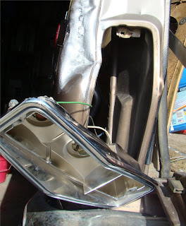
I had to return to the left taillight again. I grabbed the housing off of that same 88 GW at the PAP in San Bernardino. I think I paid two bucks for it.
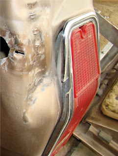
Remember what I started with (before the sidemarker fix), including the body damage. It's actually somewhat surprising that the taillight housing wasn't more damaged that this. Just that little one inch chunk missing. But my other concern, now that I had replaced the sidemarker light, I wanted to get the entire driver's side rear more waterproof than it was.
I had to pull the interior left panel in the cargo compartment to get at the two nuts holding the housing in place. Since the donor rig was already gutted back there, it was easy to see how it was attached, which made this job much easier on my rig.
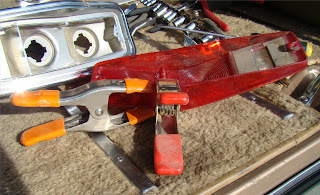
The red taillight lens was slightly damaged, as well, so I took some time to get it glued up with some silicon adhesive, guaranteed to remain intact even when exposed to moisture and heat.
The taillight lens and housing back together, wired up, and ready to go. Before I put the lens in, however, I put some clear silicon in the housing grooves where the lens mates up. Again, water tight is the phrase of the day.
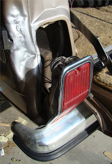
The real challenge was plugging the gap between the housing and the body panel since they were not and never would be, um, shall we say symmetrical. First, I cut up the rubber sole on an old running shoe. I shaped it like an L, as if it would fit between the top edge and outside edge of the taillight housing and the body panel. No go. Then I found some spare insulator tubing that I had leftover from when I installed my house's water heater a few years back (I get rid of very little until it truly resembles garbage). I flattened it against the outside and top edges, pushed the housing into the body panel, and tightened down the nuts. It's a great fit.

Friday, April 9, 2010

New plug wires, cap, and rotor

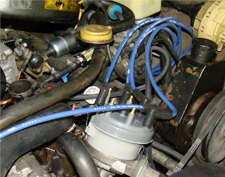
About a year ago, I bought a set of 8mm plug wires from Accel to upgrade my wiring, trying to avoid as much parasitic loss and heat as I could. The problem, unfortunately, was that the plugs I bought required male rather than female connectors on the distributor cap, so I couldn't use them. Rather than return them, I kept the wires to force me to find a solution at some point. So I've been running this style cap for the life of the Jeep.
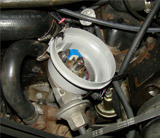
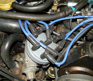
Then, through another member of IFJSA (GetLost4x4), I learned about a rather simple upgrade/fix for the male/female connectors on the cap. See, the Duraspark distributor is a Ford product, and GetLost used a larger cap and rotor that would normally go on a '79 Ford F-350 which ran essentially the same distributor. The setup begins with a mounting adapter that allows a 5" diameter cap on a ~3 1/2" diameter distributor.
Then the new cap and plugs can be mounted on there, getting me the male connectors on the cap. Basically, the cap is ultimately the same height as the original, just wider, which helps cut down on potential crossfire situations.
Done. Getting the plugs on the end of the wires (the kit was a do-it-yourself setup to customize the wire length) was easily the hardest task in this project. I strongly recommend a good pair of crimping pliers ($20 for a nice Vice Grip tool with three or so crimping options). This is just one more way of improving the wiring efficiency and reliability in the engine bay. Never a mistake to do that.

Sunday, April 4, 2010

Wiring harness--finished and running!

Double checked all connectors today, particularly around the alternator, the starter relay, and the firewall/bulkhead connection. Tightened everything down that I could. At first, it wouldn't start because it had been so long since I'd run the rig, but after a few minutes, it started up, to my great relief. But...
Then she wouldn't shut off, even with the key out of the ignition! Oops. I thought I'd created some kind of perpetual energy machine. Or, as my dad put, I'd learned how to hotwire a car (the slowest way possible).
Turns out, the old harness didn't have a clearly defined (+) line to the coil (it was lost in that awful bird's nest of wiring by the AC condensor). So when I installed the new harness, I had two hots going to the (+) side, including initially straight to the battery and not to a switched source. I've since rectified that, losing the old hot wire and keeping the new.

Installing the engine wiring harness

The first task was taking pictures of the old one, including all connectors. I wanted to mark on the new one exactly what went where before I disconnected anything. A number of photographs, blue tape, and a Sharpie made it an easy, if long.
Here's a nasty reminder of what I was trying to improve. The stuff on the fair left is the new electric fan relay. The junk in the middle is standard fair--cracked, unprotected, poorly organized/routed, and potentially dangerous.
This is what I did to the new harness as I disconnected the hold. I marked each extension and measured to see roughly where the "branches" should shoot off from the "main trunk" of the harness, if that makes sense. A significant amount of my zip-ties from the initial clean up job had to go away to allow for more efficient routing of the offshoots, but that wasn't a big deal.
I started with the bulkhead connection and the wound it back behind the engine along the firewall (there are a pair of mounting points made for zipties back there).
I wanted to keep it off of the valve covers and the intake manifold, basically the main heat sources on top of the engine. I then routed it around towards the passenger fender where the starter relay is. The main harness branches off there to go to the coil, carb, AC, and distributor. I took the time, as well, to clean up the wiring for the electric cooling fan. It's not great, but the wires will be kept together and are less like to fray this way.
I kept as much of the wiring bundled there as I could to keep the area clean. All done...

Friday, April 2, 2010

"New-to-me" headliner in today, plus sunvisors

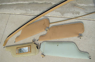
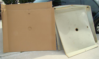
While the headliner was out for the roof rack, I decided that I might as well upgrade the headliner itself if I could (one of the previous owners was a smoker because I can't figure out how a liner could get so faded unless he was a smoker or was driving everywhere upside down.) So a trip back to that same PAP got me the donor rig's two piece liner, some trim pieces, and a pair of much nicer sunvisors.
Old vs. New-ish


Quite a difference, obviously. Installation was pretty simple. Lily and Nath helped hold it in place while I got it up and in the rail slots down the side. Then it was just a matter of reinstalling the trim pieces and the visors. To finish it up, I drilled some holes through the liner above the wheel wells to reinstall the three-point seat-belts for kiddies.
All done.

Wednesday, March 31, 2010

Spruced up the "new" wiring harness

I wanted to upgrade my engine's wiring harness to the new one available from BJ's Off-road, but it won't work with my year FSJ. The problem is that the various engine connectors changed so much during the late 80's as a result of AMC's penchant for using parts from a variety of different manufacturers from year to year (Ford distributors and carbs, GM ignition modules, etc.) and Chrysler's purchase of Jeep from AMC. My next best option was a used wiring harness that I could recondition before pulling my own, which is the route I went.
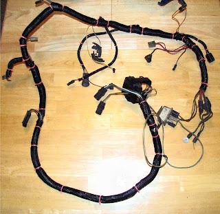
Zach at Z&M Jeeps in Ohio sent me a used wiring harness he pulled from an '88 GW. I was able to look it over on my dining room table and fix any cracked wires, clean the connectors, re-grease all metal prongs with dielectric, and wrap it in braided sleeving from Painless Performance. Here's what I started with:
It had plenty of old electrical tape and grime on it, but it was largely free of cracks. The few I found, I repaired with a double-ended crimp connector (don't know the technical name) and then wrapped 'em in fresh tape. Where needed to help hold a cluster of wires together at a branch off the main harness, I used some additional electrical tape. I then went nuts with Painless's Powerbraid and zip-ties. Yes, it's overdone, but I wanted it clean, tight, and manageable, all of which it now is. Nothing gets tangled, and I have confidence that it will flow juice where it needs to go on a consistent basis.
Overall, I was quite pleased with what I received from Z&M and with the clean up job I did. While I could have simply pulled mine and refreshed it, I wasn't inspired to trust it due to some wiring gremlins I'd had in the past and the nest of wires (mentioned and photographed in earlier posts) between the alternator and the passenger side fender. I'll keep my old one as a hopefully unneeded backup.

Wednesday, March 24, 2010

Steering box brace and roof rack

The steering box brace is one of those upgrades that will only serve a purpose off-road, but it was worth it. Right now, my steering box is performing beautifully--no leaks, easy and fluid turns, no slop in the steering wheel at all. What this brace does, thanks to TT Fabworks, is lock the steering box tight to BOTH frame rails. (It's bolted to the left rail as its standard mounting point, and this brace ties it as well to the right.) As a result, in an off-road situation the box mounting points won't be stressed or torqued much, if at all, when the tires are in a jam.
The brace is a steel tube that T's into a flat steel plate that is bolted to the inner right frame rail directly across from the steering box. My frame rail might be slightly out of true from the earlier mentioned front right ding courtesy of the PO. As a result, I had to use some Grade 8 washers to adjust the fitment of the brace against the right rail (a space is welded into the bracket to account for the offset mounting holes in the rail itself). Before I added the washers, as the brace extended over to the steering box, it didn't line up properly for the mounting brackets. Two washers later, it's good. (While we're here, note the wiring nest up above the alternator in the background. That'll be dealt with soon.)
The brace clamps around the pivot shaft of the steering box just above the pitman arm. Once it's in place and lined up, with the nut and bolt on the outside of the steering box set loosely in place, just use a pair of vice grips to hold the longer legs of the bracket in place against the extension arm before drilling holes for the mounting hardware. This gets a custom fit every time, specific to each application.
This was a half-hour project, mainly because of the alignment issues. Here you can see the brace in its entirety.

And now for the roof rack.
I found this roof rack on the same '88 GW at the San Bernardino PAP. I and several others on the IFSJA forum are picking this rig clean. It was $18 out the gate, and it's in great shape. Now, most FSJers refer to these as vanity racks because they aren't as rugged as a safari-style rack. But those are hundreds of dollars, and I don't like to carry a lot on top of my vehicles anyway, so this'll do for me.
To get the project started, I had to pull the headliner trim pieces and drop my exceptionally ugly headliner down a few inches to access the underside of the roof. Then it was a matter of disconnecting the dome lights and rear seatbelt attachment points so that I could drop it down fully.
That's when I learned a little more about the complexity of the project at hand and the usefulness for doing it. By pulling the headliner out completely, I could see the roof support cross-members, two of which were dented/sagging (the one farthest forward in this pic and the one closest to me).
Here's a closeup showing how the cross-member is supposed to be attached (with some kind of adhesive) and is bent down.
My solution of choice. I use some industrial adhesive, a 4x4 leftover from my new fence, and a small carjack to get the roof and the cross-members back into some semblance of their original position. An inelegant solution, to be sure, but I'm just looking for better, not good. Besides, I bought this thing in part because it was ugly and in need of some knuckle-busting.
Below you can see the sinkholes in the roof (those metal slats are supposed to lay flat across the roof). I just worked my way around the passenger compartment, jacking up the dents and then using some metal screws to hold the roof up tight against the slats.
In the pic above you can see the mounting holes for the rack. Apparently a little rubber grommet with a metal thread insert is supposed to go in each of those holes. As a small torq-head bolt is screwed into the grommet, the rubber expands to fill the hole and hold everything tight. Um, no. I tried and was not successful in any way. Perhaps the mounting holes were expanded by a previous owner--who knows. So plan B, which should have been plan A, was sprung into action. I found some steel L-brackets, cut them at the bend, and used them to mount the rack to the roof. Here's an undershot.
I used RTV in each bolt hole to help seal things up (you can see some squeeze out from the nearer end of the bracket). And then I caulked around every metal screw I used in the slats to hold the roof in place. It's definitely water tight and will remain so.
A shot of one of the roof rack mounting points. There's a plastic "seal" sits between the roof rack's foot and the roof itself. That also was treated to some RTV (I had a lot extra) to keep things sealed up nicely.
This thing is on securely. When I grab it and move it side to side, the entire Jeep rocks and there is absolutely no play in the rack itself. While I won't be hauling cinder blocks with the rack any time soon, it's certainly not a vanity rack anymore.
It was nice to make some improvements on the roof itself as part of the rack installation. At times, over large bumps, the roof would make a buckling sound (like when an oven cools after baking bread, if that makes sense). It doesn't do that anymore because of the increased rigidity of the repaired cross-members and the increased attachment points with the metal slats.
The final product...
Nath took this pic sitting up on my shoulders. He's quite the photographer.

Monday, March 22, 2010

Wiring up the fan

This wasn't too terribly complicated, except for the temp sensor that tells the fan relay to engage the fan itself. I didn't want it running all the time because that would only delay the engine warming up, which is part of the problem I had before with the stuck thermostat, so I had to come up with a more viable solution, which I did (by throwing a little money at the problem).
I'm not a fan of wiring nests, and the previous owner was a hack (the mess I had to clean up behind the stereo alone still boggles my mind). Unfortunately, however, the fan relay has a lot of wires running off of it, and its placement was limited by wire length (didn't want to splice any extensions on ). To keep the wiring clustered efficiently-ish and out of the way, I put the fan relay next to the starter relay on the passenger's fender inside the engine bay.
I'll probably come back to this area in the future and make some improvements in the layout and weather protection. Perhaps a plastic dome enclosure to shield it from random splashes or debris. I really don't want to damage the fan and have it die on me, leaving me stranded.
This was the slightly more complicated bit. I was hoping to use a manifold port for the temp sensor, but none were available. Essentially, this thing has to be in the coolant flow to know when the coolant temperature has reached the engagement point. It then sends a signal to the fan to turn on. (The engagement point is adjustable, which is nice.) The fan shuts off when the temp drops 10 degrees below that point, or when the engine is turned off.
My solution was to order an aluminum insert that gets put into the upper radiator hose, allowing the temp sensor to get screwed in there. There's also a ground wire to keep everything safe. I ran the wires down and around the battery and then back to the relay itself. It works, and it's out of the way of the moving parts of the engine. I'll probably wrap it in sleeving later.
I let the rig idle in the garage for about fifteen minutes, waiting until the fan engaged, which it did. The first time it spun, there was a bit of a rattle, but that sound hasn't returned since, so I'm okay with it. All in all, the new fan, the new radiator, the new temp sensor, and the new water temp sender are working as they should to keep the engine running cool and smooth.

Saturday, March 20, 2010

New Crossflow Radiator, Electric Fan, Thermostat, and Water Temp Sensor

A while back, I noticed the occasional small puddle on the garage floor underneath the radiator core support. It was a slightly cloudy liquid, not at all like I expected coolant to look like. But there was nowhere else it could be coming from. I couldn't find the leak itself, but the age of the radiator hoses and the radiator itself (which is the original with the Jeep, I believe), it was time to make an upgrade. Having worked a bit extra this winter session at RCC, I had the fun-funds to make the upgrade. I went with the aluminum crossflow radiator and accompanying electric fan from BJ's, designed specifically to fit the Jeep's core support radiator housing. This is the best shot I have of the original--apparently, it was too ugly to document closely. It's the black lumpy thing to the right of Nath's right hand.
So here are the new pieces to go in. I'm replacing both the radiator and the mechanical fan to improve cooling. Excess heat kills engines and transmissions, so this is a smart upgrade and well worth the part of the afternoon it requires to install. The fan (a 2400 CFM unit which pulls rather than pushes air) comes with the aluminum shroud to improve efficiency. Since the shroud for my mechanical fan was gone before I bought the Jeep, this is an added bonus.
I couldn't reuse the brass connectors on the original radiator because they were too small. But getting the plumbing figured out just required a quick trip to the local Home Depot for a pair of straight and elbow brass hose connectors for the top and the bottom. Here they are, installed, along with the brass connector that runs from the fill neck to the overflow container on the driver's side fender.


Removing the old one was simply a matter of draining the original (a few gallons total, but it took forty minutes to trickle drain--see pic below); disconnecting the transmission cooler lines, as well as the upper and lower radiator hoses; and then removing a few bolts holding the radiator to the core support. In this pic, you can also see the green corrosion at the bottom of the radiator (top middle of the pic). The hoses running across the upper third of the picture are the tranny cooler lines that run transmission fluid through the cooler that sits in front of the AC condenser (see next pic). The hoses that run out the left side of that mini-radiator (the tranny cooler) were also replaced in the upgrade process.
So now the radiator is in and all hoses are hooked up. This new one has a built-in transmission cooler that I chose to use with my existing/stock cooler to help extend transmission life. The tranny cooler was in much better shape than the radiator, probably because it is protected between the AC condenser and the grill, whereas the radiator itself is subject to whatever gets thrown up into the engine bay.
A shot of the underside with new hoses connecting everything together. No more leaks, much better flow, and a happy (i.e., cooler) engine. (Note the tight tolerances between the engine pulleys and the electrical fan. There's about a half inch right now because the old fan's double-ended bolts were extra long. I'll replace them with capped bolts later to increase the spacing.)

On to the thermostat.
While the radiator was drained and the hoses disconnected, I wanted to replace my thermostat (which opens and closes at specific temperatures to allow coolant to circulate around the engine). I'm pretty sure the one in there was bad simply because the Jeep took forever to warm up--a common sign the thermostat is stuck open. Here's what I found when I popped the thermostat housing off:
Not pretty. Lots of gunk and orange rust in there, at least partly caused by the fact that the Jeep has been sitting for a while. Closer inspection with the thermostat out. Looks like standing water has been sitting on a cast-iron engine block.
I scrapped off the old seal off the top of the block and cleaned up the housing, sanding it smooth and getting off what rust I can. With the engine rebuild coming soon, it doesn't need to be perfect.
A little liquid thermostat gasket, and it was back on the block, tightened down, and ready for some hoses. While I was working in the area, I also installed a new water temperature sender on the manifold just behind the distributor. This is the thing that sends the temp reading to the dashboard gauge so that I can tell how hot or cool the engine is running. I'm not sure the other one was bad, but it's an inexpensive part worth replacing in light of all the other cooling system changes I'm making.

Here it is, all back together. Up next, wiring the electric fan.


Sunday, February 21, 2010

Bumper rubber upgrade

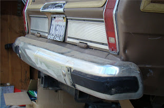
Found some good rubber trim pieces on a wrecked '88 GW at the local Pick-A-Part, same one I got the fenders from, among other pieces. My five-year-old son and I pulled my Jeep's rear bumper and then got to work upgrading it. Here's what I had to start with:
Once we got it pulled, we just had to use a socket wrench to remove the screws or nuts holding the various trim bits in place. Here's the big man hard at work...
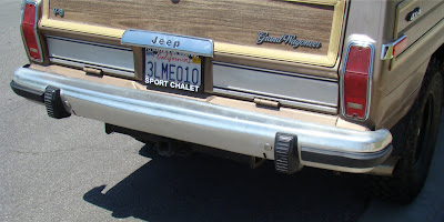
Back on and looking good.

Friday, February 19, 2010

Side marker lights

As part of the fender replacement, I had to remove the front right side marker light (which was already cracked up, dirty, and dead). Here's the gratuitous before shot:
Replacement was as easy as a call to BJ's Offroad for a new set for all four corners. I wanted, above all, to have working running lights, so I also opted for some bulbs and bulb housings. The front ones were quick and simple, with Nath helping me the whole way. The after shot, with the new fender:
The driver's side rear marker was an entirely different matter. Here's what I had to work with, thanks to the previous owner of my rig. I'm not sure what he hit or how he tried to "repair" the damage. But it was lumpy, bumpy, and quite out of true.
I couldn't get the new side marker housing to fit this mucked up area (the base is L-shaped, wrapping around the fender corner to get close to the taillight housing). So I had to get a little creative with my bandsaw. Basically, I cut off the part of the housing that wraps around the end and then scribed the remaining section to better fit the "unique contours" of the body panel. I then elongated the hole seen in the pic above (where the bulb base comes through the body to provide the bulb itself with juice) to allow for the more forward placement of the side marker base. After, I scrubbed the damaged portion of the fender around the taillight with a wire attachment on my drill to get rid of any paint flakes, followed by a quick spray of silver Rustoleum paint to retard future rusting of the area (I didn't have any gold in the garage, and I'm cheap). The final result:
Overall, I'm pleased. It works, it's sealed from the elements thanks to some clear silicon caulk, and it doesn't look bugly. I'll address the busted taillight housing later--for now, it lights up so I'm legal.